The technical input for the ROSIM-DoubletCalc3D calculation in ThermoGIS-HT-ATES consists partly of maps, partly of constant values and partly of calculated values (see figure below). The maps of the aquifers (depth, thickness) and aquifer properties (porosity, permeability and net gross) are used as input.
- The temperature is taken from the 3D temperature model.
- Water salinity is calculated depth-dependently: water salinity [ppm] = 70000/1500 × depth [m]. The salinity determines, among other things, the density and viscosity of the pumped water, and thus the required pumping capacity.
- The distance between the two wells at aquifer level is calculated for each aquifer and xy location. This is done using the thermal radius. The thermal radius of the stored volume is calculated in advance using formula 1 in Doughty et al. (1982). A fixed well spacing of 2 times the thermal radius was then used (Beernink et al., 2020).
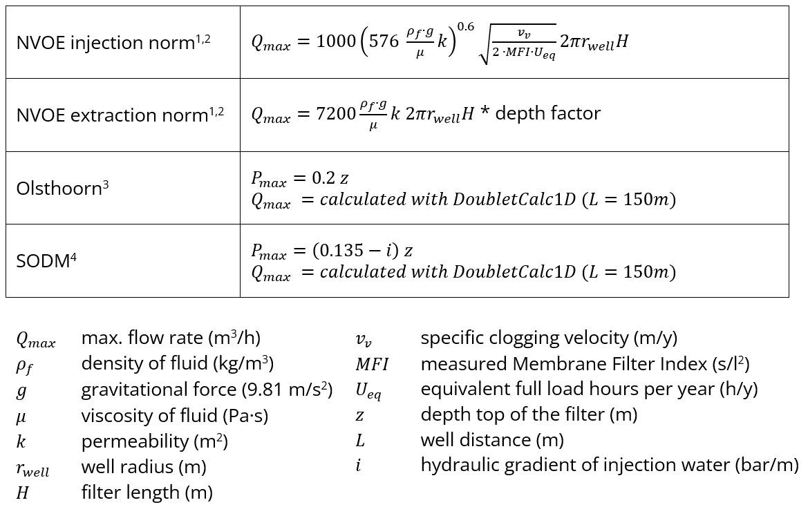
- In the absence of a good definition in the current laws and regulations, the maximum flow rate is determined using four different standards (NVOE injection standard, NVOE extraction standard including depth factor, Olsthoorn injection standard and SodM injection protocol). For each grid cell, the maximum flow rate is calculated with each standard, from which the most conservative value is then used for the specific grid cell. See New Developments or Vrijlandt et al (2023). The table below shows the formulas for the flow rate calculations.
- The total injected volume was calculated using the maximum flow rate and the number of days of HT-ATES loading. For the maps in the Mapviewer, 120 days of loading was chosen.
- The assumed internal diameter of the casing between surface and aquifer is 0.78 m (31 inch). The reservoir section is open hole with the same diameter.
- A doublet with vertical wells is taken as default.
- Currently, only the P50 (median value) is calculated.
- In the future, the option for a heat pump will be added, with this, the capacity of the HT-ATES and the quality of the produced heat (temperature level) can be improved.
- A number of cut-off values are applied in the maps to speed up the calculation. For the Brussels Sand Member, these are as follows:
- A minimum depth of 100 m and a maximum depth of 800 m have been assumed. Shallower than 100 m, the subsurface will possibly be used for drinking water production and shallow geothermal energy systems (LT-ATES, or 'WKO' in Dutch). Deeper than 800 m, a more expensive type of drilling rig is probably needed.
- At a transmissivity < 1.1e-5 m2/s (1 Dm), no calculation is done as the probability of good power output is small.
- After calculating the flow rate, no further power calculation is done if the flow rate is <25 m3/h.
- If the number of days the HT-ATES produces is <20 days, the simulation stops because very little energy will be produced and the system is unlikely to be cost-effective.
The main results of this technical analysis are maps of flow rate [m³/hr], capacity [MWthermal], energy injected [GJ], energy produced [GJ] and thermal recovery efficiency [%]. The thermal recovery efficiency is the energy produced / energy injected.

Figure: ThermoGIS-HTO workflow.
Table: flow rate calculations.